
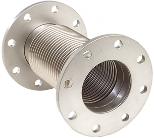
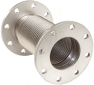
2504-2507 Low Pressure 1 Ply Bellows Joint
Information at a Glance
Series
2500 Low Pressure Round & Rectangular Bellows Expansion Joints
Material
Steel
Size
2-240 in. / 50-6000 mm
Pressure
≤150 & 300 PSI / 10 & 20 Bar
Motion
16+ in. / 400+ mm
1-Year Warranty

Other Products
 Series 9500 Alignment Guides
Product Description
• Sizes 6″ through 48″ diameter
• Austenitic stainless steel and high nickel alloy bellows
• Wide selection of end fittings
• Designed for maximum flexibility and fatigue life
• Light weight construction
Series 2500 Round Expansion Joints are specifically designed for light weight circular ducting used for engine exhaust systems, flue stacks, fan connectors, ventilation ducting and air handling systems. The bellows are designed to absorb axial, lateral and angular movements without exerting high spring forces on the system. Standard designs are ideally suited for engine exhaust duct or pipe, low-pressure air inlet and exhaust duct, flue systems, and fan inlet and exhaust connectors. The standard designs can also be adapted to special configurations with special flanges, transitions, and elbows. Refer to Series 2509-2511 3 Ply Laminated Bellows Expansion Joints for similar expansion joints with high internal damping on applications with vibration or oscillation, or for increased motions.
Design Features, N/N 2506 Shown

Common Applications
The lower expansion joint in the illustration is a typical application of a Series 2500 expansion joint installed at an engine or fan discharge. The motion for this joint is primarily lateral. Column 4 of the Design Data indicates the rated values for each configuration. Consult Hyspan for liner assistance on lateral motion applications. If the required motion exceeds the rated value, a Universal Expansion Joint should be considered as described below. For applications of this type it is good practice to add Tie Rods to the expansion joint – refer to the Tie Rod section below. The rated motions are for conditions resulting from thermal expansion. High frequency motions such as those caused by excessive engine roll or vibration may cause fatigue of the expansion joint. Consultant the Hyspan for these applications.
The two upper expansion joints shown in the illustration are axial applications in pipe or duct runs. Two or more joints are required if the motion exceeds the rated value of a single joint. The Intermediate Anchor is necessary to ensure that each joint absorbs the required motion.


Design Data
All Series 2504-2507 1 ply Expansion Joints are designed for a maximum pressure (including test pressure) of 15 psig and a full vacuum. The design temperature varies with the material used for construction.
The materials of construction for standard assemblies are Type 304 stainless steel for the bellows, van stone ends and flow liners, and A-36 carbon steel plate flanges and angle flanges, A-53 standard weight carbon steel pipe or A36 fabricated ducting. Optional materials are available including the substitution of stainless steel for flanges and pipe.

Tie rods are available as an option on Series 2504-2507 1 Ply Bellows Expansion Joints. They react the pressure thrust in piping and ducting that is not anchored such as the lateral offset application illustrated above. They may also function as Limit Rods. Limit rods do not react the pressure thrust in service but they are designed to react the pressure thrust in the event of an anchor failure. Their main function is to limit the axial extension and compression of the bellows to the rated values. Hyspan normally refers to both tie rods and limit rods as Tie Rods but the factory settings are important – factory settings as Tie Rods do not permit axial extension but limits compression to the rated value of the bellows. Factory settings as Limit Rods will permit axial extension and compression in accordance with the rated travel specified in the Design Data.
Flow liners or internal sleeves are optional features that are available for all configurations. Liners provide a means of isolating the bellows element from direct contact with the flow and as a result eliminating flow induced vibration, minimizing pressure loss, and creating dead air space between the bellows that insulates the bellows. Flow velocity and operating temperature are important for calculating the correct liner thickness and construction. Standard EJMA liners are rated to 100 FPS at 200 F. Most exhaust and air applications exceed these values requiring specially calculated liners. Thermal expansion applications typically include large axial motions with limited to no lateral when anchors are mounted to the pipe or duct centerline. To maximize flow and minimize pressure drop when liners are ordered, the standard liner ID is set to allow ¼” lateral, or the lesser lateral rating, when used with schedule Standard pipe. For greater lateral offset, or additional liner assistance, consult Hyspan.

Hyspan installed flow liners follow the recommendations outlined in the Standards of the Expansion Joint Manufacturers Association (EJMA)summarized as follows:
• EJMA maximum flow without a liner for gaseous service is: 12 FPS for 3” NPS, 16 FPS for 4” NPS, 20 FPS for 5”, and 24 FPS for 6” NPS and larger. Above these values liners are required, advise velocity and operating temperature.
• Standard liners are rigidly attached on the upstream end of the expansion joint and open on the downstream end. If reverse flow conditions exist, the liner thickness must be very heavy gauge or a telescoping design should be used.
• If the expansion joint is installed is a vertical run and the flow is upward, drain holes should be added at the lowest point of the liner to avoid trapped liquid.
• Unless a special oversize bellows design is used, the flow liner will intrude into the pipe or duct flow path. If the expansion joint motion is axial only this intrusion will be minimal, and the liner inside diameter may be comparable to the adjacent pipe or duct.
• If there is lateral or angular motion the gap between the liner outside diameter and the bellows inside diameter must be great enough to allow for this movement – see illustration.
• Connectors designed for axial compression with flow liners must be designed so that the liner does not extend beyond the end of the joint, or the downstream pipe is cleared when the liner protrudes – see illustration.
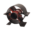
Series 2500 Universal Expansion Joints are two bellow elements separated by a pipe spool. They are designed primarily for lateral movement. Unlike a single expansion joint that absorbs lateral motion by reshaping the bellows centerline, universal joints absorb lateral motion by angular displacement of the bellows elements. As a result, as the joint length increases, the lateral motion capability increases and the forces and moments acting on the adjacent equipment decrease. The application of a universal expansion joint is a very effective method of absorbing lateral motions with minimum loading on equipment.

Since most low pressure piping and ducting is not as rigidly anchored and guided as high pressure systems, tie rods are recommended for universal expansion joints. Tie Rods react the pressure thrust, protect the bellows elements from over extension or compression, and control and react the weight of the center spool. The illustration shows the stops that limit the travel and the center spool support.

Longer tied universal expansion joints typically have to supports on each rod to guide the center spool. In addition the expansion joint can be incorporated into pipe runs where the expansion joint extends the length of the run, and the expansion of the run is absorbed within the tie rods as well as absorbing the expansion of the adjacent run by lateral offset.
Hyspan does not catalog standard Series 2500 Universal Expansion Joints designs because they are normally designed to meet the available length. Consult the Hyspan or the Hyspan Sales Representative in your area for assistance.
Ordering Information

Refer to the illustrations (2504, 2505, 2505 or 2507) above for the configuration required. Refer to the Design Data table for the available motions, spring rates, lengths and weights.
Example:
24″ nominal diameter
Single fixed flange,
Standard bellows material, 304 stainless steel
Standard flange material A-36 carbon steel
3.0″ axial compression, 1.5″ axial extension
(2505L-086-3.0 with Flow Liner)
Hyspan products are available from Sales Representatives and Distributors, or they can be purchased direct from the factory. The minimum factory order for open account customers, COD shipments, or bank card sales is $100.00 (USD). All major credit or debit cards are accepted. The minimum order for new account applicants is $100.00. Our Confidential Credit Application can be downloaded and forwarded to Hyspan for processing. All orders are subject to the following Terms and Conditions, and the above warranty applies to all material. Please read these documents.
Confidential Credit Application, can be completed on line.
